
This post describes a project I undertook to build a home-grown, Arduino-based, WiFi-enabled lawn sprinkler controller.
I don’t know about you, but I’m never happy with my lawn sprinkler schedule. In Austin, it can rain till my garage floods one week, then return to the typical four-year drought conditions with 100°F+ temperatures for the rest of the summer. As we progress through the drought stages, we go from being allowed to water whenever we want to twice a week to once a week. I also find that the consumer-grade zone controllers have really crappy user interfaces, they are often limit you to either an “every X days” pattern or watering on specific days of the week (but not both), and they tend to limited in how many events are associated with a given zone…not to mention you have to go out to your yard – or maybe your garage if you’re lucky – every time you want to change the schedule.
Well, a while ago my controller died again (I think I’ve gone through three of them now),

Tethered Arduino UNO sprinkler controller and Triac board
so I decided to build something better. My first iteration was an Arduino UNO connected to a second-hand 8-port Triac controller board which drives the sprinkler solenoids (they operate on 24V AC). The Arduino was tethered to my pc via USB (the controller enclosure box happens to be just outside my home office window) and I cobbled together a custom C# GUI for maintaining the schedule for my six zones and sending on/off signals to the Arduino via a simple serial protocol. This worked pretty well, except my PC had to be running for any watering to occur. In the summer in Texas, if you miss a week because your PC was off, you can kiss off your vegetable garden. The lime tree your wife gave you for your anniversary 10 years ago will probably be half dead too, and then your in the doghouse. Trust me.
Anyway, before long, I grew tired of the tethered solution -I came to the conclusion that I needed to ditch the tether.
At first I was thinking along the lines of using the same PC-based UI, but having it send the schedule data to the Arduino, where a more sophisticated sketch would store it locally somehow, then determine the on/off times independently of the PC. This would require a place to persist the data in case of power failures and reboots, plus a real-time clock (RTC). As far as I could determine, there’s not really a way to persist variable data over reboots with the UNO; you can’t persist dynamic variables in the flash RAM from the sketch itself. This led me to consider other Arduino clones that include some EPROM.
As I thought about it further I also wasn’t really that fond of having to tether to the thing just to update the schedule. I realized that a way cooler solution would be to WiFi-enable it. To make a long story short, wanting WiFi and some kind of persistent data store led me to look at Arduino compatibles combined with WiFi shields.
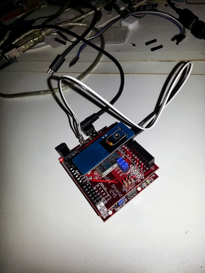
As it happens, my company, National Instruments, recently acquired Digilent. Among other things, Digilent makes a line of very nice Arduino ‘compatible’ boards, the chipKIT series, that run PIC32 processors (see my post regarding driving addressable Christmas lights with an Uno32). As an employee, I get special pricing that makes these pretty attractive, but they’re pretty affordable even at list price. They also have a Wifi shield and, although the chipKIT boards have no EPROM, the WiFi shield includes an SD slot. You can use use the SD slot to store static web pages, but I can also persist schedule data by writing it to file on the SD card. In hindsight, it’s also clear that a faster processor is pretty much necessary for serving up web pages…it’s still a little slow even running on the PIC32, which is an 80Mhs, 32bit processor…way faster than the ATMEGA368 (sorry, Arduino). I chose the Arduin form-factor chipKIT uC32 combined with the chipKIT WiFi shield.

Complete Assembly: a uC32 Microcontroller card, WiFi shield with Micro SD card and DS1302 daughterboard

DS 1302 with pullup resistor from I/O line to +5V
For a real-time clock, I went with a really cheap module from dx.com which incorporates the DS1302 chipset. As of this writing, it can be found here, but there are many similar inexpensive boards out there. I scrounged up some examples, as well as an Arduino library or two, for interfacing with the DS1302, but when I would try to make it work interfaced to the uC32, I was getting flake behavior. It worked fine on a true Arduino, however. After googling forever and trying all kinds of things code-wise, I finally stumbled across a thread or two which hinted that I might need to add at least one pull-up resistor. Eureka! Apparently the Arduino has internal pull-up resistors on I/O lines, but I guess the uC32 doesn’t – I added a 4.7K pullup from the DS1302 I/O line to the +5V pin and it immediately started working fine. I connect the +5V and Gnd pins to the corresponding pins on the USB side of the uC32 via a small ribbon cable. I also bent those pins back at 90° so that i could just plug the remaining 3 data lines directly into the female header on the WiFi shield.

DS1302 connected to Gnd and +5 pins on uC32
DS1302 daughterboard attached to digital IO pins 37, 38 & 39 on uC32 and Wifi shield
Originally, I thought the problem was software -related. I figured the DS1302 libraries I was finding just weren’t compatible when compiled for the PIC32 – so I wound up writing a really simple custom one and that’s what the project currently uses. I now realize it was probably a hardware issue all along, so shortly I’ll update my code to switch my homegrown one out for one of the libraries already floating around out there like this one or this one. In retrospect, I suppose I could have just used Digilent’s Real-time Clock/Calendar PMOD.
Along the way, I made another discovery – the chipKIT boards also have a non-obvious, poorly publicized feature – you can solder a 32.768Khz crystal onto the board which enables an embedded real-time clock! (see http://hacking.majenko.co.uk/node/33) Support for using it is included in the chipKIT MPIDE libraries. I went ahead and bought a pack of 20 from China for about $6 and tried this out…it also works fine! Just for the hell of it, I wrote a wrapper library that will work with either one, depending on which #DEFINE you un-comment in the project’s App.h file – so the sprinkler code works with either. Keep in mind the embedded clock does not retain the time over power interruptions, though, so you would have to provide a backup power source. With this in mind, a separate daughterboard is probably a better bet.
The project software consists of a sketch and related modules developed in the chipKIT MPIDE (available for download on Digilent’s website). This is a version of the Arduino IDE which is compatible with the chipKIT product line. I’ve open-sourced the code and, as of this writing, the source repository is hosted here: https://code.google.com/p/wifi-sprinkler UPDATE: Google has shut down their google code repository. The new location of the code is hre: https://github.com/acoulson2000/wifi-sprinkler.
A significant portion of the project is code which implements a very basic webserver. Implementing an HTTP server from the ground up in C probably would have been beyond my capability; fortunately, Digilent’s Gene Apperson has written a basic implementation which I was able to use as a starting point. As of this writing, that basic server code can be found here. Since starting this project, I’ve been in touch with Gene Apperson, and subsequently Keith Vogel, at Digilent. Keith has put together a somewhat more robust version of the HTTP server which would really be better to use…I just haven’t had time to go back an re-implement on that foundation. Maybe someone out there would be willing to take that effort on? The new version supports concurrent connections, which would probably improve page load time. It is not been published just yet – I will post the URL here when it is.
Disclaimer, I am a Java guy – not a C guy – and this project got way deeper into C code than your average Arduino sketch, so I am not at all proud of the code I hacked out and will happily accept improvement contributions. I think I’ve ferreted out all the buffer overruns and pointer issues, but I’m by no means certain.
One other note regarding developing the sketch: By the end it had become really cumbersome. The project includes so many libraries, it takes about 50 seconds to compile and upload. Add to that about 30 seconds for the WiFi to connect and you’re looking at almost 1 minute and a half in ‘build time’ every time you want to make a change and test it. I feel like with projects this complex, using a “real” IDE, like MPLAB, with an inline debugger interface would save a ton of time. This would be even more true if you could emulate the WiFi connection…although I suppose you could use a plain old Network Shield during much of the development.
In an effort to keep the back-end lean and simple, I designed the web front-end to be a static web page which relies on AJAX calls to simple services on the server. The page is rendered once and includes some basic jQuery libraries. After initially being rendered, all updates and actions are handled via AJAX calls to simple service urls on the server (with JSON responses, where needed). All the html, javascript, css and image files are stored on the SD card and served up from there. The service URLs are handled via custom code added to Parser.cpp and Render.cpp. The ongoing activity of waiting for schedule on/off times and activating/deactivating zones control pins is handled in App.cpp. Once loaded, the main page, index.htm, performs AJAX http GETs to server services to store schedule changes, manually turn zones on or off, and to get the date/time as well as system status (which it does every 10 seconds).
In order to avoid long delays whenever the page first loads, I also tweaked Gene’s server code a bit to support browser-side caching of javascript, css and image files. This involved returning some cache-specific headers in response to the first request for such files in Render.cpp and watching for the “If-Modified-Since” request header coming back from the browser in Parser.cpp. If we get that header, we just return a 304, instructing the browser to use it’s cached copy. This results in much snappier refreshes after the initial load.
To interface with my 24V sprinkler solenoids, I use a 2nd-hand triac board similar to the one I used in my Christmas Lights Suit, accept that I use the 8-triac version that the author, Mark, mentions here. You can see it in the top of the first photo, above. Of course, you could build your own…triac control circuits are quite simple (example here). Note that Mark’s boards require an inverted signal – so they are OFF, when the input pin is HIGH, ON when it is LOW. To facilitate using this board, but also have the code be compatible with other boards that might be “active-high”, I provide two settings in App.h, INVERT_PINS and INVERT_MASTER_PIN. Set them to true for inverted signals, false for non-inverted.
Here’s a screenshot of the final product:

WiH20 Console Screen Shot
So that’s about it – the interface seems to be working pretty well, so this weekend I intend to swap the tethered UNO out for this solution. I encourage anyone who’s interested to help me improve the sketch. Again, the code repository is at https://code.google.com/p/wifi-sprinkler – you should definitely start with the README. In there I’ve called out a number of improvements that would be nice. Within a few days, I’ll hopefully have integrated a ‘standard’ DS1302 library instead of my cobbled-together on. I’ll also be trying out the WF32, a new board just released by Digilent that combines the PIC32, WiFi and SD all on one card.
UPDATE: I’ve now received the WF32 and switched over to it. This is a really nice board – it even includes some nice additional on-board features like more LED’s, some push-buttons, and a potentiometer, as well as a host-mode USB port…all for only $69 retail.

Digilent WF32
The transition was mostly painless – one problem I did run into is that you have to get a build of MPIDE more recent than the 07152013 distribution currently on the Digilent site. On the WF32, the i/O pins used to communicate with the SD card are different. I obtained a more recent version of the SD library files directly from the source repository here: https://github.com/chipKIT32/chipkit-core . Once I overwrote the library files under the chipKIT MPIDE install directory with the latest from the GIT repository, it worked like a charm! I also tweaked to pins used for the indicator LEDs a bit, since those onboard the WF32 are not the same as the uC32 (my latest code build will automatically detect which version and set the pinLedConnect and pinLedInitialized variables appropriately). One last thing I will do is solder some pins into the currently empty in-circuit debugger jumper at JP2 to provide power to the DS1302 daughterboard. I’ll then swap out my current, tethered Arduino and my sprinklers will be fully WiFi-enabled 🙂
I’m considering throwing together an Android app for viewing/controlling this guy too…check back later!

Pingback: A WiFi-Enabled Law Sprinkler Controller using the chipKIT WF32 | chipKIT Development Platform
Pingback: chipKIT, sprinkler, controller, uC 32, Wifi shield,
Very nice project! please keep us (people interested in your project) updated. I’ll try to implement something similar to your project, so ill be bothering you with some questions. Thanks for sharing!
Nice. Question: Do the Relays Controll the Remote Solenoid Valve at the Sprinkler Head by WiFI
or is the WiFI Relay linked to the Solenoid by Low Voltage wire the Old School way. Thanks.
Looking to implement a WiFi Solenoid system.
THe Digilent board is connected directly to the Triac board..so 5V connections to the triac board…then the triac board is connected directly to the solenoids. I went with the triac board because, although the voltage that turns on a solenoid is only 24V, it’s still AC, plus I had the 8-port board lying around. Some people do seem to have success with mosfets, but 5V relays would probably be easier and less likely to damage your Digilent or Arduino board. The whole assembly is housed in a weather-resistent box mounted outside near the valve box and connects to my WiFi from there.
i´ve been trying to get this sketch running for a couple of days now and i haven´t been able to, I keep getting this compilation error related to the szpassphrase(after several modifications of the code and one specifical library httpconfig.h). could you help me get this aplication up and running? i just need a very general step-by-step guide to get to the configurations needed to get the sketch to work.
programming in not my strongest but i would really like to have this sketch working so i can tweak it for other aplication. if i get them to run i would gladly share the with you too =)
regards from México
pat
Sorry, I just noticed this question – haven’t been blogging much lately. Hopefully you’ve made progress, although you may also know that there are some other open source sprinkler projects out there. I’m sure the project could be made more straightforward – I just haven’t had much reason to work on it. It pretty much does what I need and I’ve just left it alone. It’s kind of hard to tell what the issue might be on the limited information you gave. If you still feel like getting it going, my suggestion would to start very simple – only changing the wifi SSID and passphrase – and work from there.
Nice project 🙂 since I did something similar I am leaving you my respective project link here: https://jwothke.wordpress.com/2016/05/08/and-now-to-something-completely-different/
Nice. Where did you source your waterproof boxes? I’m looking at another project where I want to have outdoor sensors.